Repairs, FDD Not Working, Battery Damage
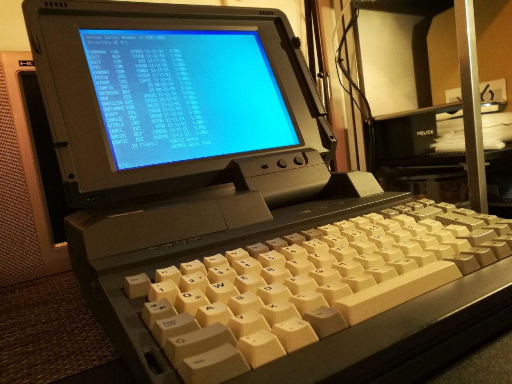
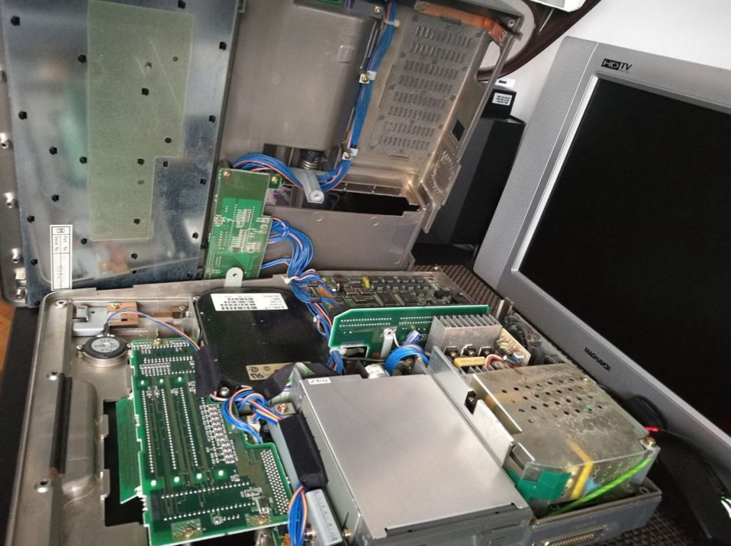
The Amstrad ALT-286 is a very nice machine, its a mix between the TOSHIBA T3100/20 and the SHARP PC-4500.
It shares same technology like the two mentioned above but the display its superior due to the fact it came on the market almost 3 years after the Toshiba and Sharp. Even if it was more budget oriented the computer has a lot of features and the quality build is impressive.
I got this computer from a local sales site and the computer was stated as working. The amount requested was 699 LEI, that means in EUR 155. I called the seller and he was OK to sell it for 40 EUR.
Short technical description
Processor: 80286
Screen: VGA LCD 640*480 Pixel
Graphics: Cirrus Logic
Memory: 4x 1024 KB Max
Harddisk: 20 to 60 MB
FDD Drive 720 KB FD-235HF
Extensionslots VGA
AT Keyboard
FDD Floppydrive
System: DOS 3.3 and DOS 5.0
Printerport Centronics
Weight: 7 KG
Issues
This computer had seen better days, the HDD spins up but OS is not found, and the FDD is not working for sure as it has a very unlikely sound when booting and it does not spin the floppy disk.
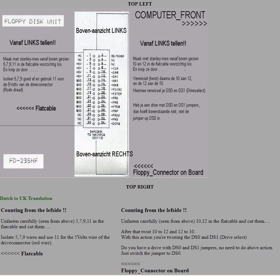
I will take the computer apart and I will replace the HDD and the FDD unit. The FDD unit can be replaced but there is a custom mod you have to do on the Floppy cable. I found an interesting article of someone that replaced the original unit with a standard one.
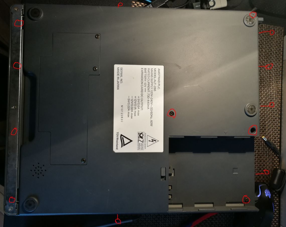
Step 1 Disasembly
Remove the screws from the bottom \ back and aside.
Step 2 Remove top cover
To do this you need to have your screen in OPEN position and then just lift the top cover from the bottom and put the cover on a side like in the photo. The display cables are pretty long so you can leave it like that or remove the cables to fully take apart.
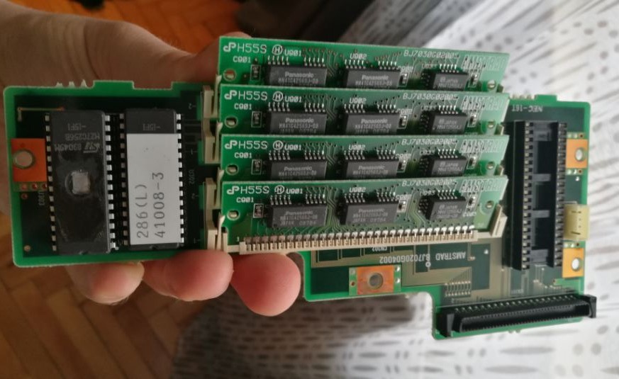
STEP 3 REMOVE EXTENSION MODULE
For this you need to remove the 4 screws in the picture and just lift up the socket on the right top of the module. (this is not mandatory but you need space to remove the FDD)
STEP 4 REMOVE FDD UNIT
Remove the 5 screws and lift up the FDD unit.
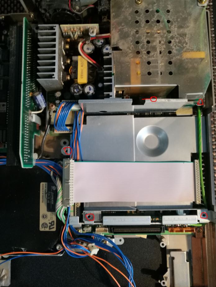
STEP 5 REMOVE ALUMINUM COVER
Next part is to remove the aluminium cover (note that this cover has also the role to spread the heat of the chips)
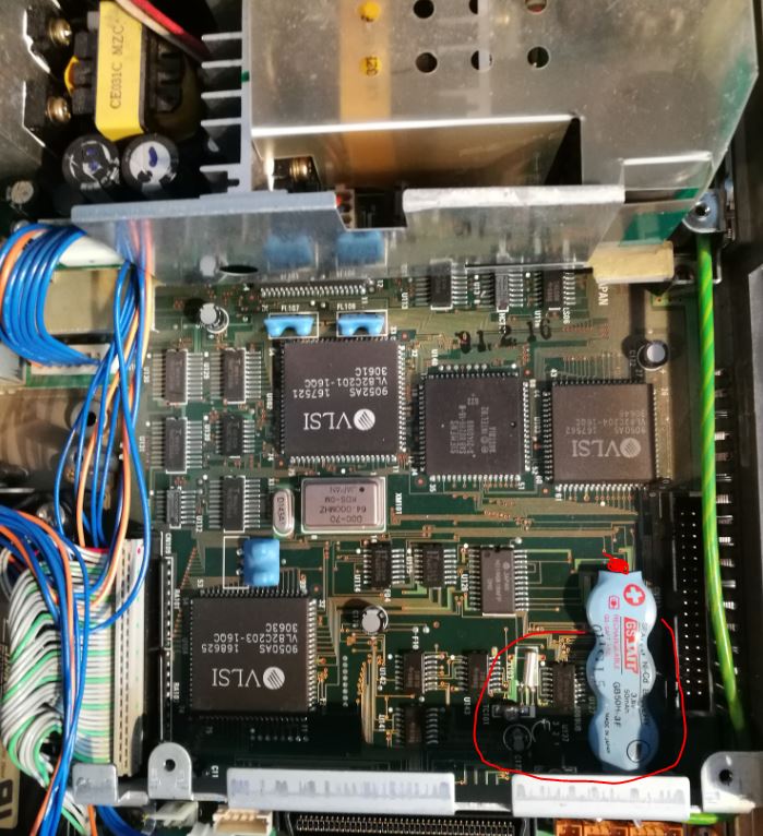
Even if the battery looks in sharp condition you have to remove it. If it hasn’t leaked, it will! So just replace it or cut it off. I just removed it cause I use this computer rarely so I just don`t care the setup will forget the HDD config or the clock…
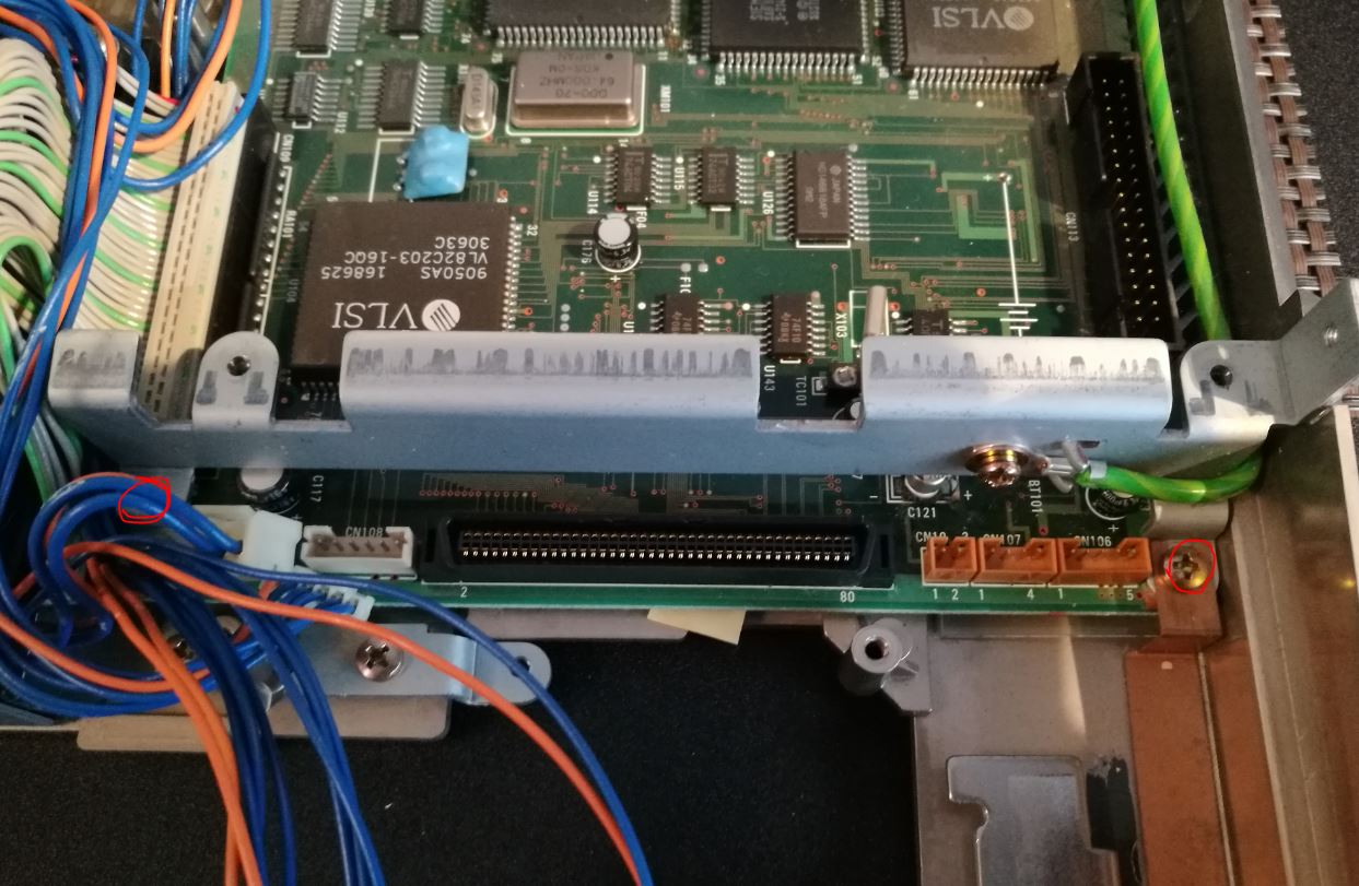
STEP 6 REMOVE METAL FRAME
Next part is to remove the metal frame like in the picture below:
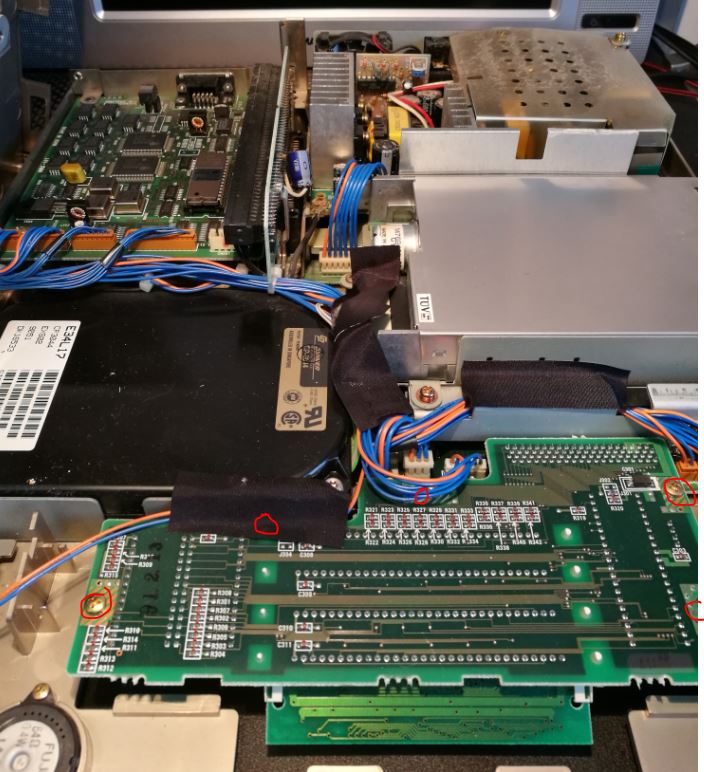
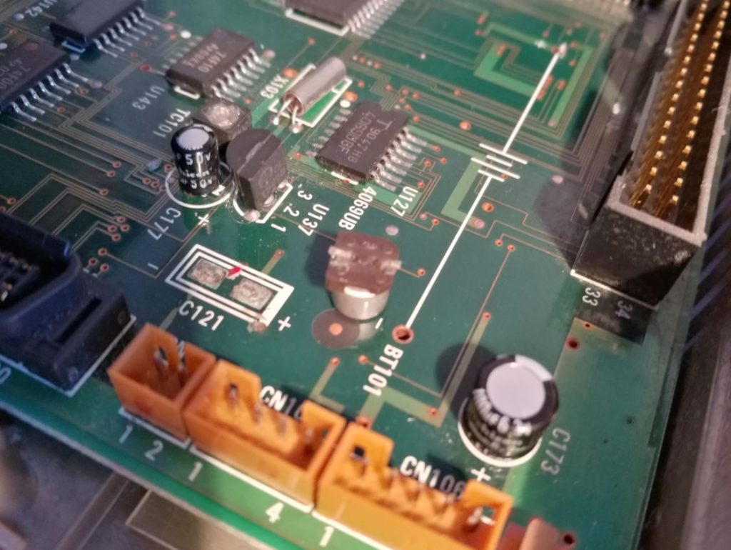
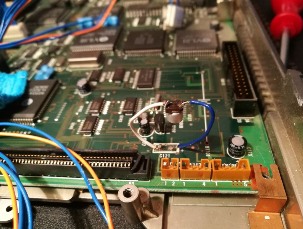
STEP 7 BATTERY DAMAGE REPAIR AND SOLDER NEW CAPACITOR IN PLACE
STEP 8 FDD REPAIR
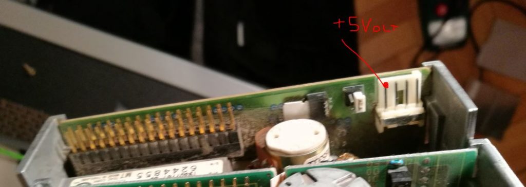
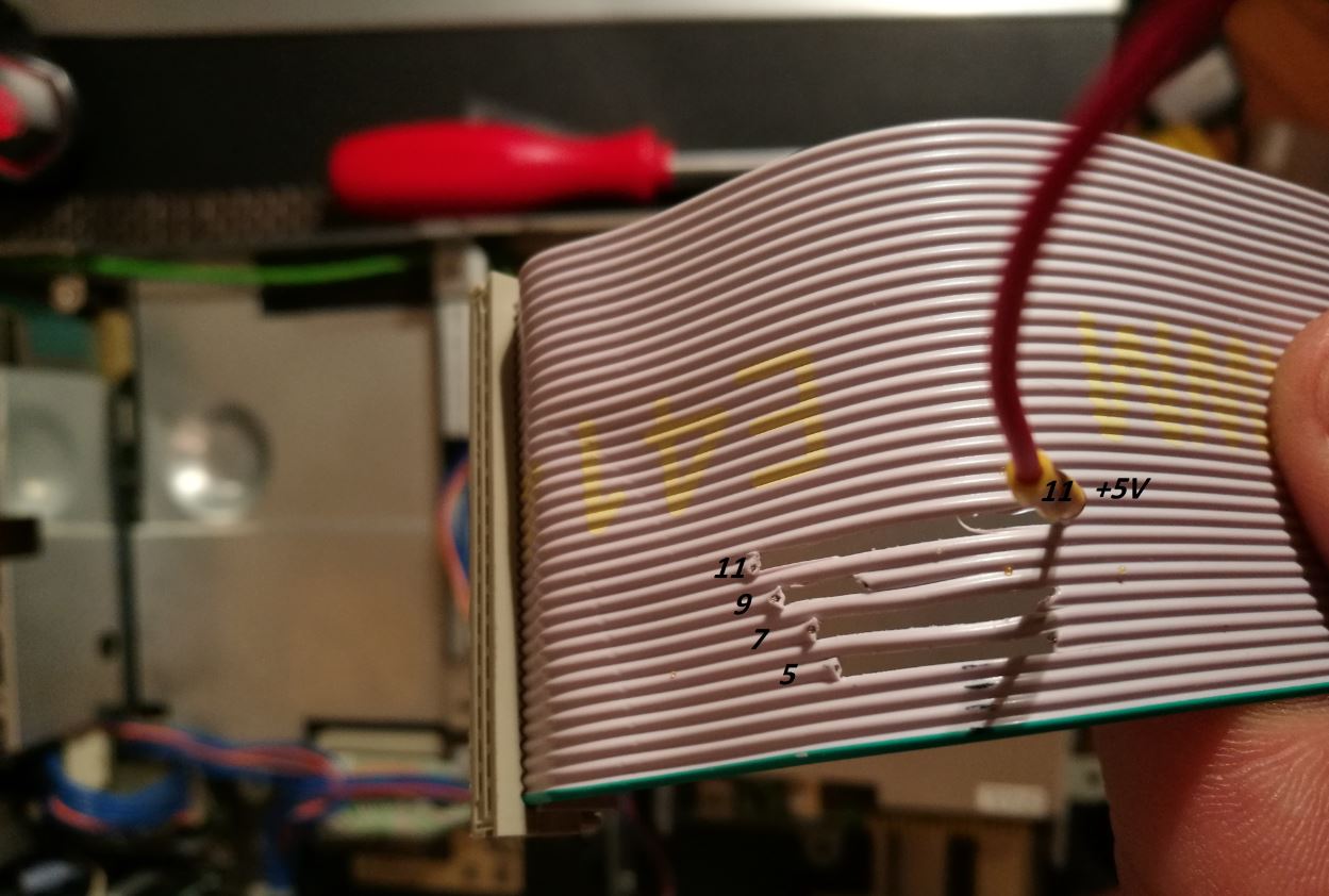
Basically you need a standard 3.5 FDD, I got one with the DS jumper so for me its very easy to make the mod. Basically I just have to remove 5 7 9 11 wires stated in above diagram and get the +5V on the new FDD unit.
IF YOU DO NOT HAVE THE DS OPTION
Cut 10 and 12 and reverse 10-12 \ 12-10
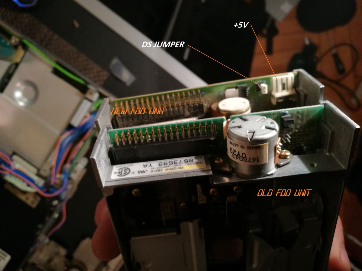
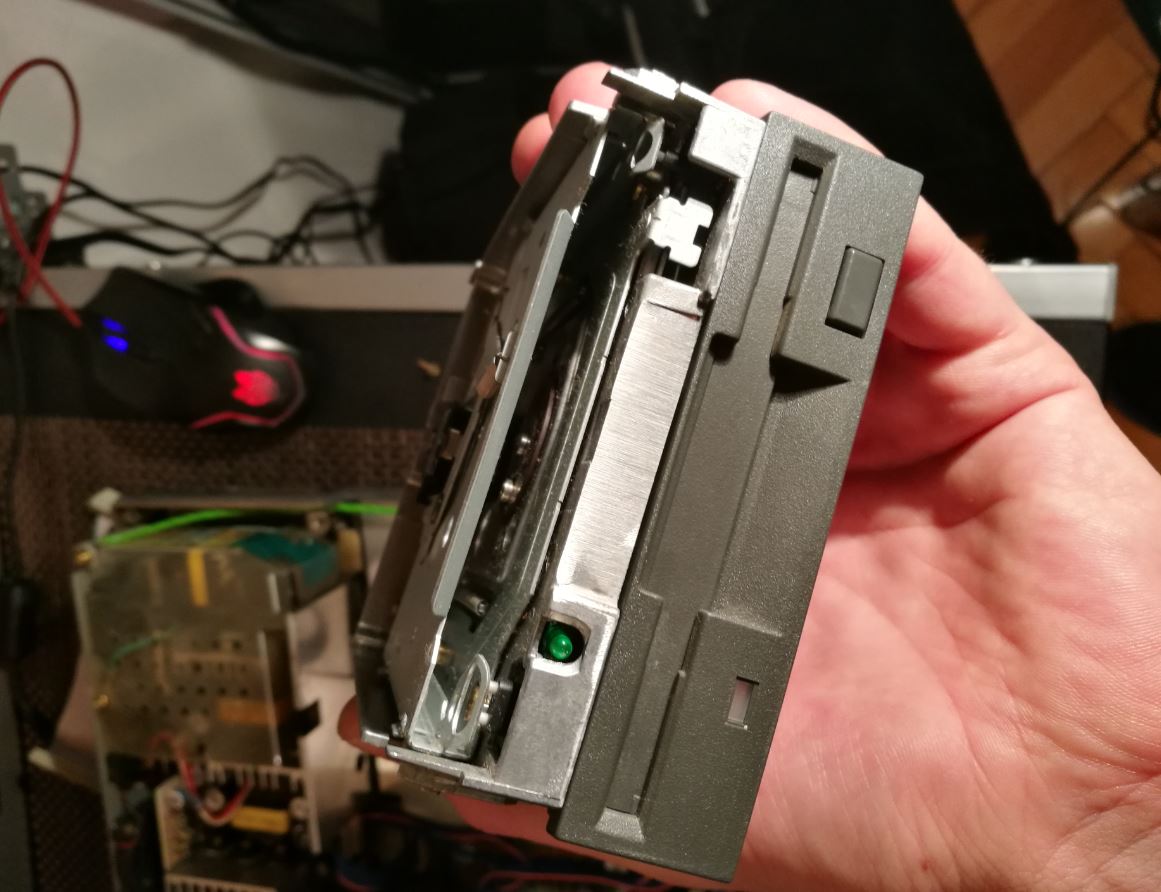
I was able to change the plastic front ornament from one to another, they are both made by TEAC company.
I think the picture above is very descriptive and for those who are technical people will manage easy.
Where my hand is is the connector that fits the motherboard.
I had put some isolating tape just to make sure the wires won`t touch something inside the computer.
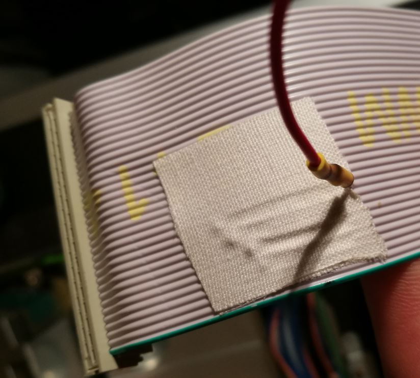
Now Place the red wire on the +5V connector on your new Floppy Disk.